CAD MODEL
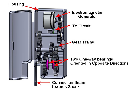
The energy harvester consists of five major parts: several gear trains, two one-way bearings, an electromagnetic (EM) generator to circuit, a connection beam, and housing, all of which are shown below. These parts have their purposes for our design. Gear trains are used to convert the low speed and high torque at the knee into high speed and low torque for the generator. Two one-way bearings oriented in opposite directions can selectively transmit the input torque from different rotating directions through two different gear trains. The EM generator which is a three-phase brushless motor can output AC voltage if there is rotation input. The connection beam that is fixed on the shank is used to transmit the input torque from the knee motion. The housing is used to protect all parts of the energy harvester from damage.
Overall Design
This project took a lot of research and brainstorming to put together. However, the end result of the design made all of our hard work and research worthwhile. With a blend of creative engineering and real life practices, we achieved great results within budget.
Dimensions and Views
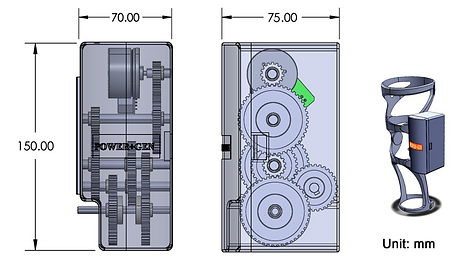
This device has a compact size that the wearer feels comfortable while walking. The overall dimension is 150 X 70 X 75 mm. It has a rectangular shaped housing that holds the gear train with one way bearings, electromagnetic generator and the circuit inside. The image displays the overall design and how it will be mounted on a knee brace.
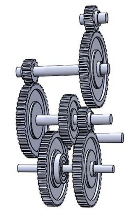
Gear Trains
Energy harvesting efficiency is a key challenge. During walking, the motion behavior of knee joints is like that of an inverted pendulum, in which the direction of angular motion is opposite during the swing and stance phases over one gait cycle. In order to harvest all the negative energy from both the swing and stance phases in gait cycles while maintaining the wearer’s comfort, we proposed and developed a novel transmission system, which has the functions of motion rectification as well as amplification. It can convert the bi-directional input torque from the knee into uni-directional rotation at the EM generator.
Clockwise Rotation
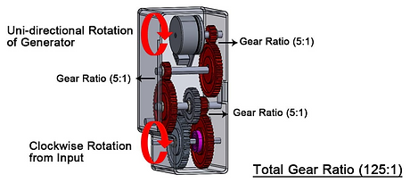
There are different rotations from input and gear numbers for the two gear trains. The input is in a clockwise rotation in swing phase and its transmission has three-stage gears. The total gear ratio is 125:1, and the one-way bearing makes sure the gears only rotate during one motion of the knee.
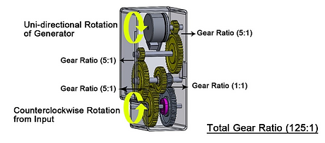
Counterclockwise Rotation
The input in a counter-clockwise rotation is in stance phase and its transmission has four-stage gears. The total gear ratio of this phase is also 125:1, and the one-way bearing makes sure the gears only rotate during the second half of the knee movement. Overall, the components work together to unify the rotation direction at the generator. As a result, the internal torque at the transmission system caused by the rapid change of motion direction from the knee can be significantly reduced. The efficiency of energy harvesting is improved as all the negative work from the swing and the stance phases in the gait cycles can be harvested.
Material Selection
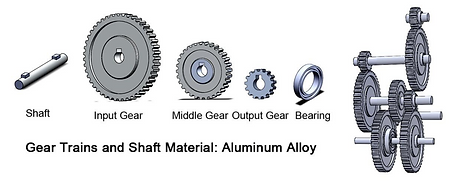
The gear trains and shafts (including two one-way bearings) will be manufactured using aluminum alloy. This material has very good properties for our design. The first one is the cost: even though aluminum alloy is not as cheap as plastic, it is easy to machine in order to offset the material cost. Second, is the weight: aluminum alloy is only one-third the weight of steel alloys of the same size so that the wearer feels comfortable while wearing it. Third, is the transmission accuracy: metal gears transmit high gear ratio more accurately compared to plastic gears. Finally, the strength and durability: aluminum alloy has a high strength-to-weight ratio. This will be tested through FEM analysis in Solidworks.
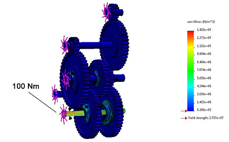
FEM Analysis
The maximum input moment generated by knees is 40 Nm. In order to ensure that the proposed transmission system in our design run safely and securely, we increase the moment to 100 Nm over the input shaft in our simulation running in Solidworks. The stress result of FEM analysis indicates that the stress of the whole system made of aluminum alloy is much less than the yield strength, which means that not only does the material aluminum alloy we choose satisfy our requirement, but also our transmission system is safe and secure enough to protect the wearer during the use.
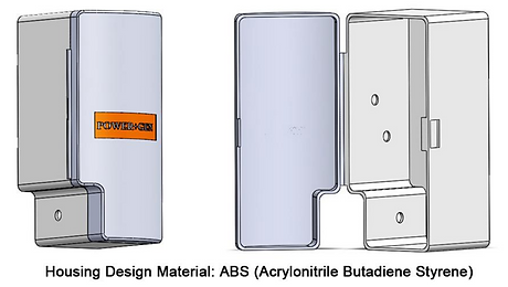
Housing
This housing is designed to keep all the components inside the device safe and secure. The housing can be easily opening and closing by using a buckle. When the housing is closed, it protects the energy harvester from bumps, dust, water, and dirt in times when the wearer is walking; when the housing is open, it is easy to show the wearers the interior overview and allow them to repair the product during failure. The housing will be manufactured with ABS (Acrylonitrile Butadiene Styrene) due to its cost, weight, strength and durability.